Understanding Activity Models and Functional Hierarchy.
The folks developing the ISO STEP AP233 specification for exchange of systems engineering data determined that there are really only two fundamentally different ways to model behavior.
- Function-based, functional flow, or causal chain based models: These kind of approaches define individual “functions” that transform inputs into outputs, which can then be strung together in chains. Data, information, or energy can flow though these chains, being modified and transformed along the way by each function. Functions can also generate control signals to modify the behavior of the chain, or of other functions. This kind of behavior modeling is represented by a variety of approaches, inluding Behavior Diagrams/SREM, N2 charts, Hatley-Pirbhai, and UML Activity Models.
- State-based, state flow, finite state machine, event-based, or hierarchical state chart (Harel) based models: These kind of approaches define certain states in which actions or functions can occur, but don’t concentrate on the functions themselves. Actions also occur when entering and exiting states. Moving between states is the fundamental way of triggering behavior. Each state may have sub-states, some of which may exist in parallel.
State flow techniques are much more prevalent when modeling software behavior. This is likely because the semantics are very precise, and lend themselves well to generating code. State transitions are easy to determine, and can trigger any kind of behavior, including software subroutines. It has also been suggested that state based models have an implicit physical solution in mind… when defining a state, one could immediately ask “state of what?” This question has no real meaning in software, but it has serious implications in systems engineering.
Modeling more abstract behaviors, such as a business operation, combined forces campaign, or even a simple air intercept, have proven to be very difficult to using state flow! Our operational or war-fighting customers tend to think more in terms of functions (verbs) when describing what they need, rather than states (nouns or gerunds). They tend to resonate with functional flow models rather than state machines, which hide the functions on the transitions. The majority of systems engineers seem to resonate better with functional flow models, and have at least a passing familiarity with functional flow block diagrams (FFBDs). Starting the functional definition process with functional flow using UML/SysML activity models has proven to be a successful strategy. Here is an example for a video encoder from a famous textbook:
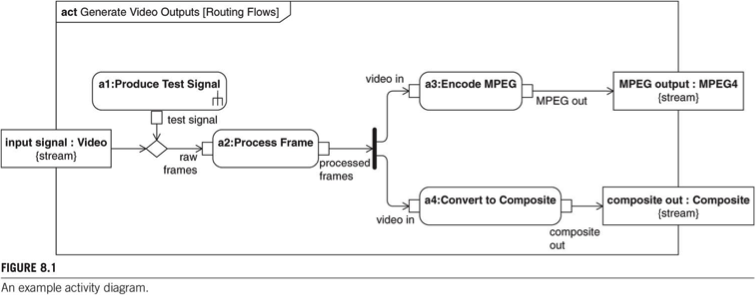
The flows represented in this diagram represent data/information/energy. Adding control flow would have unnecessarily complicated the example. I will update this post with a link to some excellent JOT articles on activity modeling. Please note that SysML/UML activity diagrams represent use. The round cornered boxes on the diagram are NOT Activities! They are Actions… The diagram frame is the Activity! Also note that in SysML, the word Activity is synonymous with the word Function.
What about Definition? Well, most of the time activity models are built without regard to functional hierarchy. Almost every tutorial on activity modeling avoids the hierarchy issue. In this activity diagram, however, you will note that each Action has a colon in its name, similar to the way Parts are named on an ibd… That was done deliberately to indicate that each action is technically a “Call Behavior Action”, which in turn invokes an Activity in it’s own right. For example, Action a2 invokes the Activity Process Frame. This particular notation is unique to SysML, and does not appear anywhere in UML. The “rake” on the Action a1 indicates that the Activity Produce Test Signal has its own unique activity diagram, which in turn has its own Actions… Thus, a hierarchy of function! SysML was intended to provide a mechanism for displaying that hierarchy (or definition) of function, independent of the context in which actions invoke (or use) the functions. This is how you build a functional hierarchy or functional breakdown in SysML using a bdd:
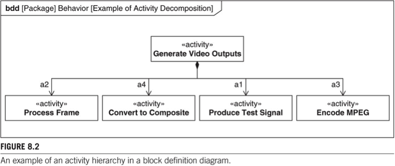
Note how this definition and use of function in act/bdd is similar to the definition and use of structure in ibd/bdd. Even the use of role names on the bdd (a1…a4) is the same. This is a cognitive triumph in SysML! Unfortunately, some meta-model arcana got in the way of implementing this cleanly, and most tools don’t support this automatically. SysML 1.4, due for adoption in 2014, is specifically bolstering this definition/use paradigm, and should make it very implementable… even beyond just behavior and structure.
For the time being, here are my recommendations for activity modeling:
- Don’t put an Action on an activity diagram without having it call an Activity…. Use only CallBehaviorActions on activity diagrams, and make sure they call Activities that have already been defined. If you are sure that Activity you want doesn’t exist yet, define it first, and then call it from the Action.
- Manage all the Activities in a separate set of packages in the model, just like blocks. I like to have a separate package for “Behavior”.
- Don’t ever use package structures to define functional hierarchy…. Generate functional hierarchies using composition relationships on bdds. The Activities can all be at the same level, a kind of grab bag or pick list. If you need to break them up into packages, do that by similarity of function, not by composition!
Maintaining a separate “list of available functions” will make your overall set of activity models more consistent, and maintaining the hierarchy (definition) on bdds along with the context (use) in activity diagrams will ensure a more cohesive, flexible model overall.
Recent Comments