SysML was intended to provide a standard graphical modeling language for systems engineering. Many different modeling techniques/languages had previously been used for developing system models, such as Behavior diagrams, IDEF diagrams, N2 charts, Hatley-Pirbhai architecture diagrams. Tools have tended to support only one of these techniques/languages.  As a result, the systems engineering discipline has lacked a broad-based standard that to support general purpose system modeling needs.

The Unified Modeling Language (UML) was chosen as a basis for SysML for several reasons.  It had become a de facto standard for graphical modeling within software engineering, UML tools and training had become widely available, and the OMG standardization process already supported UML customization for specific domains (e.g. Real-time, SOA, etc.)

The Systems Engineering Domain Special Interest Group (SEDSIG) was jointly sponsored by INCOSE and OMG in 2001. Development of SysML followed a well-structured engineering process, starting with a Request For Information (RFI), then the development of a systems engineering conceptual model (2002), and a period of requirements analysis.  This was followed by the development of a Request For Proposal (RFP) for the UML Profile for Systems Engineering (2003), which laid out clear, detailed requirements for any graphical language intended to support systems engineering.   Any proposal to the OMG needed to demonstrate compliance with the requirements in this RFP.  After the SysML specification was initially developed, an independent panel of INCOSE and OMG experts evaluated this compliance.  SysML 1.0 was adopted by the OMG in 2006, and the subsequent widespread adoption by industry indicates that it has met the objective of being a broadly useful system modeling language.

Even though the deployment of SysML has generally met with great success, the following conceptual issues have been found to recur sporadically when SysML is taught in the classroom or deployed on programs:

  • SysML is too complex! (understanding the scope of initial deployment, flexibility vs. Complexity)
  • What does that darn diagram header mean? (understanding models vs. Diagrams)
  • Why do I need both ibds and bdds? (understanding definition vs. Use)

○  Activity diagrams have no activities on them! (understanding activity modeling vs. Functional hierarchy)

  • Why not use packages for my product breakdown structure? (understanding composition vs. Containment)
  • How is SysML different than Matlab? (understanding descriptive models, analytical models, and parametric modeling)
  • Why do I care about Units? (values, value types, units and quantity kinds/dimensions)
  • Why isn’t SysML executable? (modeling functionality vs. Model execution)

There are certainly other conceptual issues that crop up from time to time, but these seem to be the most prevalent.  The following sections will explore these issues one at a time.

How much SysML do you really need to know?

The complaint is frequently heard that “SysML is too complex” and “It is impossible for non-software, non-UML systems engineers to learn!”  This typically comes from folks who aren’t familiar with system modeling at all, rather than those with modeling experience who could be considered qualified to judge the complexity and adequacy of a modeling language.    Their implication is that they need to understand ALL of SysML in order to use ANY of it.  This is the fundamental stumbling block this blog entry intends to address.

Here is the scope of diagrammatic complexity the SysML learner is confronted with when trying to understand the various diagrams encompassing SysML:

1.diagram taxonomy

This is consistent with UML, and should be a small logical step for the UML literate modeler.  But it can be understandably daunting to the systems engineer who is unschooled in modeling.  Do they have to understand the subtleties of all of these diagrams?  Of course not!  This “standard” taxonomy also does not consider the similarity between the various diagram types.  Much of the angst that new SysML learners experience can be relieved by pointing out that there are really only three diagrammatic concepts that they need to learn in order to start modeling:

2.diagram tax descr

  1. Arrangement and connection (use), as shown on internal block diagrams and parametric diagrams.  This is the most intuitive, boxes-and-lines representation.  Everyone “gets” this, because it is a standard “system block diagram” notation.  It only gets confusing when the student is prematurely foced to think about typing parts via blocks, or typing ports.  The basic untyped part and connector is always easy to grasp.  Unfortunately, in the long run, these simplistic concepts aren’t very useful.  The concept of blocks typing ports is appropriate to introduce after the student has put the third part on an IBD with the same name.  If the parts really are the same, then the instructor has an entre into discussing blocks as a way of defining parts.
  2. Containment, composition, and taxonomy (Definition), as shown on block definition diagrams, package diagrams, and requirements diagrams.  This starts to introduce new symbols that a systems engineer may not be familiar with, such as black-diamond composition.  However, every engineer is familiar with the concept of parts lists.  Most people “get” bdd’s when they are presented as a parts hierarchy.  The subtleties of role/part names vs. Block names can be explained as part number vs. Catalog number, e.g. “R5 is the drain resistor in the circuit.  It is a 500ohm, 1/4 watt resistor, Jemeco catalog number 1967344”.  1967344 is the block and provides the definition, R5 is the part and provides the context/use.
  3. Most “old school” systems engineers are familiar with functional flows of some kind, and are less comfortable with state machine representation.  Functional decomposition can be accomplished using activities on bdds.  Functional flow needs something like activity diagrams.  Yes, there is a convention here to learn that is different than IDEF 0, N2, or other formats… But it does include “old school” concepts like segregating control and data flow.  “old schoolers” familiar with Operational Concept Diagrams already know about swimlanes, and should be pretty comfortable picking up activity diagrams with swimlanes/partitions.

These three diagrammatic concepts are all that are normally required for a new-to-modeling systems engineer to begin to be productive.  It doesn’t have to be intimidating!


Understanding the difference between diagrams & models

PowerPoint & Visio teach us to take diagrams at face value.  Diagrams in these tools can be manipulated independently, arbitrarily modified, and easily abstracted.  Anyone can add whatever they want, without rigor or process.  As a result, we treat a set of diagrams as unrelated pictures.  The better modeling tools tend to reinforce this impression… They provide a palette of drag and drop symbols and line types, and even include resizing and shading options just like Visio or PowerPoint.  This is great from a user familiarity perspective, but terrible from a model integrity perspective.  These tools make it much easier to create a new “box on a diagram” (and corresponding model element) than to find and use an element that is already in the model.

It has been found that mature modelers work mostly from the model browser to populate diagrams, rather than from the tool palette.  In general, it has proven to be good practice to create a model element in the browser first, making sure it is in the package where it needs to be, and then drag that element from the browser on to the diagram.  Mature system modelers often scorn using the tool palette, and populate most model elements in the browser without using a diagram at all!  This is analogous to creating the parts list before working on the assembly drawing, and it serves to instill an appropriate level of rigor in the modeling process.  By building the package/containment structure for the model first, before building a single diagram, the modeler has a better sense of the model as a whole.  By populating the initial set of model elements into this structure, the modeller is already invested in maintaining that structure, and already knows where to find things in it.  It is even possible in most tools to create relationships between model elements in the browser, but that tends to be more easily done on diagrams.

Once the modeler has the structure of the model firmly in mind, the diagrams become merely convenient views into the model.  Each modeling tool is capable of rendering or updating a diagram directly from the model, including following the various relationships (like composition) and rendering the related model elements on the diagram.  When these new elements appear, most tools have a variety of auto-layout options for arranging them… but none are totally satisfactory.  Diagram layout is the domain of human aesthetics, and machines just aren’t there yet.  Tools can also render existing relationships between elements already displayed on a diagram, but that requires an extra step on the modeler’s part.  Relying on this diagram rendering capability really starts to expose and exercise the power of building models in the first place.  The modeler becomes focused on the model, not the diagram.

It is also important to remember that reports, scripts and checkers run on the Model, not the diagrams!  It doesn’t matter how pretty the diagrams are if the model is inconsistent.    Modelers who really focus on the model soon realize that tables and matrices are also excellent model viewers.  For example, advanced system modelers very rarely want to see a requirements diagram, and prefer to see requirements in a table of some kind.  They  also tend to  prefer to see allocation relationships in a matrix, rather than on a diagram.

This emphasis on model vs. diagram doesn’t mean that we have to ignore everything we learned using Visio or PowerPoint!  Good modeling practices are consistent with good diagrams, and the following principles still apply:

  • Minimize number of elements at each layer of abstraction (5-7 elements is the standard practice)
  • Elide unnecessary information on the diagram… use views/viewpoints to aid with auto-generation.  Try to make a diagram fit on a single page/screen
  • Give the diagram a meaningful name!  Be explicit about what it is supposed to represent.

Diagram frames are, in my mind, one of the most useful and meaningful advances of SysML over UML.  SysML requires EVERY diagram to have a frame, and the frame actually means something… The diagram frame represents an element already in the model, so the frame provides a context to understand everything inside it. The diagram header is used to specify exactly which model element the diagram frame represents.

3.diagram header

There have been complaints about how cumbersome it is to read these diagram headers… but once the modeler is thinking in terms of the model, rather than the diagram, the information in the header is invaluable!

Understanding definition & use.

Object Oriented principles provide some powerful techniques for defining families of systems.  These have been around these so long that to many engineers they seem obvious, almost second nature.  Two OO principles that I find particularly useful are composition and generalization, which SysML combines together in an approach to structural hierarchy.  The implication of this concept in SysML is something that the author usually refer to as “definition vs. Use“.

Internal block diagrams (ibds) are all about use.  They depict the interconnection connection of “parts” within the context of the containing block represented by the diagram frame.  This diagram shows that the block Anti-Lock Controller is composed of part d1 and part m1 connected by the connector c2, with d1 giving/sending something and m1 taking/receiving something.  It further shows that d1 is a Traction Detector, and m1 is a Brake Modulator.  It does not define what Traction Detector or Brake Modulator mean.

4.ibd

Block definition diagrams (bdds) are, as the name implies, all about definition.  They define context-invariant relationships and attributes, including “is a” (Brake Modulator is a Electro-Hydraulic Valve) and “has a” (Anti-Lock Controller has a Traction Detector and a Brake Modulator).  “Is a” is generalization, “has a” is composition.

5.bdd

“Definition vs. Use” seems to be the biggest “stumbling block” for new SysML users that don’t already have a software background.  They can even be problematic for some OO savvy people!  Any introductory SysML class will usually have at least one question along the lines of “Why do I need BOTH a bdd and an ibd?”  The notions in each diagram seem to overlap.  The diagrams seem to be redundant.  If the student is experiencing too much frustration with this concept, a fruitful response has been… “If you need to ask the question, just build the ibd and be done with it!”  Once they have built a suitably complex model, the role of the bdd will naturally become clear.

Generalization and composition aren’t necessary to define a system.  Ibds are intuitive analogs to the old, familiar “system block diagrams” that systems engineers have been using since before there were computers.  Bdds are NOT mandatory, but you will eventually want them.  Why?  Because you get tired of fixing the large number of ibds that you have generated.  You get tired of having to go into each ibd and update the name of a part or port specification so that it is consistent with a new design change.  As soon as someone asks “Couldn’t we just have all the part names in one place, and collect together all the ones that are basically the same?”  then they are ready to build their first bdd!  Yes, building the bdd later will cause some rework.  It is always more efficient to build them first, before the ibds… But that’s not always appropriate for students trying to learn SysML for the first time!

Bdds and ibds are complimentary aspects of a single structural model.  This definition-use paradigm applies more broadly than just structure, however.  It also applies to parametric & activity models, and in SysML 1.4 will apply even more broadly.  Activity models and functional hierarchy will be discussed in a subsequent section.

The real efficiency of definition-use can be summarized as follows:

  1. Define an element in only one place in the model.
  2. Use it everywhere it is needed.  Don’t redefine it unless you need to.

Mechanical engineers tend to have fewer problems with this concept.  They are used to the idea of establishing a parts list first, and to the idea that they must choose their parts from some kind of parts library.

Understanding Activity Models and Functional Hierarchy.

The folks developing the ISO STEP AP233 specification for exchange of systems engineering data determined that there are really only two fundamentally different ways to model behavior.

  1. Function-based, functional flow, or causal chain based models: These kind of approaches define individual “functions” that transform inputs into outputs, which can then be strung together in chains.  Data, information, or energy can flow though these chains, being modified and transformed along the way by each function.  Functions can also generate control signals to modify the behavior of the chain, or of other functions.  This kind of behavior modeling is represented by a variety of approaches, inluding Behavior Diagrams/SREM, N2 charts, Hatley-Pirbhai, and UML Activity Models.
  2. State-based, state flow, finite state machine, event-based, or hierarchical state chart (Harel) based models: These kind of approaches define certain states in which actions or functions can occur, but don’t concentrate on the functions themselves.  Actions also occur when entering and exiting states.  Moving between states is the fundamental way of triggering behavior.  Each state may have sub-states, some of which may exist in parallel.

State flow techniques are much more prevalent when modeling software behavior.  This is likely because the semantics are very precise, and lend themselves well to generating code.  State transitions are easy to determine, and can trigger any kind of behavior, including software subroutines.  It has also been suggested that state based models have an implicit physical solution in mind… when defining a state, one could immediately ask “state of what?”  This question has no real meaning in software, but it has serious implications in systems engineering.

Modeling more abstract behaviors, such as a business operation, combined forces campaign, or even a simple air intercept, have proven to be very difficult to using state flow!  Our operational or war-fighting customers  tend to think more in terms of functions (verbs) when describing what they need, rather than states (nouns or gerunds).  They tend to resonate with functional flow models rather than state machines, which hide the functions on the transitions.  The majority of systems engineers seem to resonate better with functional flow models, and have at least a passing familiarity with functional flow block diagrams (FFBDs).  Starting the functional definition process with functional flow using UML/SysML activity models has proven to be a successful strategy.  Here is an example for a video encoder from a famous textbook:

6.act

The flows represented in this diagram represent data/information/energy.  Adding control flow would have unnecessarily complicated the example.  I will update this post with a link to some excellent JOT articles on activity modeling.  Please note that SysML/UML activity diagrams represent useThe round cornered boxes on the diagram are NOT Activities!  They are Actions… The diagram frame is the Activity!   Also note that in SysML, the word Activity is synonymous with the word Function.

What about Definition?  Well, most of the time activity models are built without regard to functional hierarchy.   Almost every tutorial on activity modeling avoids the hierarchy issue.  In this activity diagram, however, you will note that each Action has a colon in its name, similar to the way Parts are named on an ibd… That was done deliberately to indicate that each action is technically a “Call Behavior Action”, which in turn invokes an Activity in it’s own right.  For example, Action a2 invokes the Activity Process Frame.    This particular notation is unique to SysML, and does not appear anywhere in UML.  The “rake” on the Action a1  indicates that the Activity Produce Test Signal has its own unique activity diagram, which in turn has its own Actions… Thus, a hierarchy of function!  SysML was intended to provide a mechanism for displaying that hierarchy (or definition) of function, independent of the context in which actions invoke (or use) the functions. This is how you build a functional hierarchy or functional breakdown in SysML using a bdd:

7.bdd

Note how this definition and use of function in act/bdd is similar to the definition and use of structure in ibd/bdd.  Even the use of role names on the bdd (a1…a4) is the same.  This is a cognitive triumph in SysML!  Unfortunately, some meta-model arcana got in the way of implementing this cleanly, and most tools don’t support this automatically.  SysML 1.4, due for adoption in 2014, is specifically bolstering this definition/use paradigm, and should make it very implementable… even beyond just behavior and structure.

For the time being, here are my recommendations for activity modeling:

  1. Don’t put an Action on an activity diagram without having it call an Activity….  Use only CallBehaviorActions on activity diagrams, and make sure they call Activities that have already been defined.  If you are sure that Activity you want doesn’t exist yet, define it first, and then call it from the Action.
  2. Manage all the Activities in a separate set of packages in the model, just like blocks.  I like to have a separate package for “Behavior”.
  3. Don’t ever use package structures to define functional hierarchy…. Generate functional hierarchies using composition relationships on bdds.  The Activities can all be at the same level, a kind of grab bag or pick list.  If you need to break them up into packages, do that by similarity of function, not by composition!

Maintaining a separate “list of available functions” will make your overall set of activity models more consistent, and maintaining the hierarchy (definition) on bdds along with the context (use) in activity diagrams will ensure a more cohesive, flexible model overall.

Understanding Containment vs. Composition.

We naturally tend to think of containers in terms of composition, like a car being a container for wheels and chassis and engine… But that’s not all that containers can be used for.  Good modelers need to distinguish the structure of the product being modeled from the structure of the information about the product being modeled.  UML/SysML Packages are generic containers, and we use these containers to organize the information in the model.  An object can be contained in one and only one container, but can be used (or composed) just about anywhere.   In fact, using Packages to represent the physical structure of the product being modeled is a very bad idea, from an object-oriented perspective!

Consider a Russian doll… a larger doll that has a slightly smaller doll inside it, identical except for its size.  The smaller doll has an even smaller one inside it, etcetera.   The “inside-ness” relationship of one doll to another should be considered composition, just as a car is composed of chassis, driveline, and engine.  Now, this could be modeled as a series of packages, each containing a “doll” block and another package, which in turn contains another “doll” block and another package, etc.  One would then have to set up a separate composition relationship between each of the “doll” blocks on a bdd.  On the other hand, to emphasize the “sameness” of the dolls, the doll “system” could be modeled as a single “doll” block, with a composition relationship to itself.  The “doll” Block would have a “size” parameter which would be recursively re-specified by the whole-part composition relationship.  Clearly, this is a much more compact approach.  Now if all the dolls need to look like Boris Yeltzin, the modeler only has to change one block!

A very compelling feature of SysML models is that they can simultaneously support multiple hierarchies. The product structure hierarchy, the product function hierarchy and the model packaging structure may be completely different within a single model!  This is part of the power of Object Oriented thinking.

Composition vs. Containment is a common issue for even experienced modelers. The containment relationship is depicted using a crosshair notation, but it is seldom seen on diagrams.  More commonly, containment is shown by graphical nesting.  Here’s an example of both notations:

8.pkg

Containment is the basis for package structure in the model browser.  Blocks and Requirements can also have containment relationships, but modelers are advised to exercise caution when using them.  It is wise to use only Packages when generic containers are needed.  Containment carries with it the concept of “ownership”, and it plays a role in change management.  Changing a model element generally requires write access to its container, i.e. The package that contains it.  Containment also determines where the model element “lives” in the model, or its Namespace.  UML/SysML requires that a model element name be unique, but only within its namespace.  Any element within the model can thus be uniquely identified by its namespace (path) and its name.  A Qualified Namespace is a specific way of identifying the namespace within the model, and is written with double colons thus: ACME Surveillance Systems Inc::Products::Cameras::Behavior, referring specifically to the Behavior Package in the diagram above. Every model element in the Behavior package will need to have a unique name.

It is this containment relationship is the basis for the Package hierarchy that every modeling tool depicts in the browser window.  Once again, this is NOT composition… It doesn’t represent “inside-ness” or assembly structure of the product we are modeling, but rather a filing structure for all of the related product information.  We should be free to reorganize the filing structure of this information without having to modify how the product is assembled!

9.browser

Here are some alternative approaches to package/containment structures.  These are really just alternative “filing systems” for the model information.  Single user models benefit from a very simple package structure, as seen on the left.  When the model gets more complex, with multiple levels of abstraction, the package structure may morph more towards the middle.  As more modelers get involved with the same model, the issue of containment/ownership will become increasingly important, and the structure may eventually migrate more toward the right.

10.model_org

Composition, on the other hand is a way of representing a whole/part relationship.  It is shown as a black diamond relationship on a bdd.  This was covered earlier in the definition and use topic.  Composition role names on the bdd correspond to part/action names on the ibd/act.  The following are some groundrules have proven useful for composition:

Groundrules for Product Structural hierarchy

  • Treat every block as reusable
  • Put them in a package structure where modelers can find them… based on what they are, not how they are used
  • Build ibd’s from blocks in the browser (drag & drop).  Autorender the bdds after the ibds have been built.
  • Untyped parts are poor modeling form
  • Put FlowSpecifications or InterfaceBlocks in the hierarchy too

Groundrules for Functional hierarchy

  • Treat every activity as reusable
  • Build act’s (activity diagrams) from activities in the browser.  Then build the bdds.  Most tools won’t auto-render bdds, so this will be a little more work.
  • Maintain a Data/Info Model for typing items and messages
  • Enforce all data types in one convenient containment hierarchy/package structure.  This is your data dictionary.

Understanding descriptive models, analytical models, and parametric modeling.

There are many sub-specialities within the systems engineering discipline.  Modeling and simulation specialists, analysts, requirements engineers, architects, IV&V engineers, Reliability Maintainability Safety & Supportability (RMSS) engineers, front-end, back-end, etc. We really are a diverse collection of skills, and sometimes, these skills get stovepiped.  MBSE is one technique that can facilitate cross-connecting these stovepipes.

SysML was built to support the construction of “system models” that are fundamentally descriptive in nature, that is they contain the same level of information that would have been found in description documents and specifications, such as the System/Segment Description Document (SSDD) or System/Segment Specifications (SSS).  The emphasis is on maintaining a consistent overall representation of the system, with carefully controlled levels of detail or abstraction, and ensuring that each subsystem and its interconnections are adequately described to enable consistency within the more detailed design.  Terminology, data definitions, and interfaces must all be maintained in a structured and consistent way.  Once the system model has been developed to an appropriate level of detail, these documents can be automatically generated from the model using the modeling tool’s scripting language or report writing capability.  The system model, in this context, clearly caters to the needs of the system architect and requirements engineering skills within systems engineering.

When systems engineers need to perform performance analyses or trade studies, however, they need a different sort of modeling capability.  Because the focus is on analysis rather than description, these models are referred to as analytical in nature.  They are not intended to provide a baseline for total system design, but rather to answer a specific technical performance question or provide data for a particular design decision.  As such, they don’t need consistency in terminology, interfaces, or level of detail… rather, they need enough fidelity and physical understanding to provide the necessary outputs.  These analytical models can be either static (representing properties in a manner independent of time, such as a table or spreadsheet), or dynamic (representing how properties vary over time, perhaps using a system of dynamic equations).

11.descr-ana

One or more dynamic models may be composed into a simulation, which also includes a set of initial conditions and a simulation engine to control and monitor of the execution.  Tools like Simulink provide a simulation environment that supports these three elements.

12.mod_sim

Clearly, the development of simulations for the purpose of analysis should be informing the overall system architecture, and decisions resulting from this analysis should somehow be reflected in the descriptive “system model”.  The following diagram explores some desirable relationships between the descriptive/specification (system) model, built in SysML, and the set of analytical models and associated simulations.

13.mbe

SysML was designed with this interface to analysis firmly in mind.  The parametric modeling capability in SysML has proven to be a flexible way to connect the structural, behavioral, and requirements aspects of the descriptive system model with the broad spectrum of analyses necessary to ensure a valid and feasible overall system design.

This paper is not intended to be a tutorial on parametric modeling, but rather an introduction to the concept. The following simple example may be illustrative.  Note that just like structure and behavior in SysML, parametrics can be modeled using both definition and useDefining parametric constraints (so that they can be reused) happens on a bdd:

14.air_comp_par

Note here that a the Constraint Flow Rate Equations represents a reusable set of equations, possibly even hierarchically defined, which can potentially be applied in many different contexts.  In this case, Flow Rate Equations are applied specifically to the Flow Rate Analysis block.  The Flow Rate Analysis  references Air Compressor Context as the context for the analysis, which (not shown here) provides access to all the value properties available within the air compressor structure and behavior… Such as various capacities, pressures, power, etc.  This bdd, being a diagram of definition, does NOT indicate specifically indicate which value properties in the structural/behavioral models are connected to which parameters of the constraint equations!  For that, we need a diagram of use, or a parametric (par) diagram:

15.air_comp_par_diag

The SysML specification does not provide any inherent mechanism for solving or evaluating the sets of constraint equations, but most tools have implemented some capability in this regard.  A growing number of tools, such as Phoenix Integration’s mbsepak and Intercax’s SLIM/paramagic/Melody, provide a direct dynamic linkage between SysML parametric models and a broad spectrum of analysis tools, simulation environments, and mathematical solvers.  I must note that these two companies provided this capability based on industry demand… meaning that there are an increasing number of sophisticated system modelers making heavy use of parametrics to drive and iterate system designs.

When this capability to link the system description to the system analyses works, it is much more impressive, meaningful, and powerful than simply animating the SysML descriptive model!  There is a separate section below about the stumbling block of “executable system models”.

So what is the “stumbling block”?  I have found that systems engineers who build descriptive models tend not  to build parametric models!  Sometimes, they use spreadsheets or tables of key parameters (KPPs, CPs, TPMs, MOEs), but the opportunity for directly linking to specific analysis models is so much richer, and could be so much more productive!  As vendors provide increasingly better support for parametric model connectivity to analysis & simulation, systems engineers have fewer and fewer excuses for NOT documenting key performance relationships in parametric models!

Understanding Values, Value Types, Units and Quantity Kinds/Dimensions.

“A model without values has no value”  – Dr. Darren Kelly

This topic is a natural follow-on to the previous parametric modeling discussion.  When modeling systems at an abstract level, it is usual to define a set of attributes or parameters that will be important in driving design.  Examples include Measures of Effectiveness MOEs), Measures of Performance (MOPs), Key Performance Parameters (KPPs), Critical Parameters (CPs), and Technical Performance Measures (TPMs).  Please not that defining these parameters is not the same thing as assigning values to them… the actual numbers that drive or represent the performance of the system design.  Assigning or computing these values is one of the key objectives of requirements/performance/feasibility analysis.

Unfortunately, quite a number of system models never get past the abstract attribute phase… and never included real values!  In a way, the presence of numerical values is an indicator of the maturity of the model.  How, then, are values actually represented in a SysML model?  Well, once a Value Property (a.k.a. attribute) has been defined in a SysML model, most tools provide a field where a number can be entered directly.  This field technically should be titled “Initial Value”, since it doesn’t represent the actual value of the property in all circumstances and contexts.

For example, let’s say we are modeling an automobile in Rhapsody, so we define a Block named Automobile, and a Block named Tire.   Even if the car has four of them, we only want one definition of Tire.

16.tire_bdd

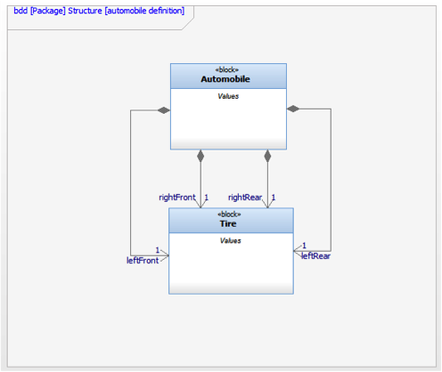
Then we define a Value Property (attribute) of Tire named Pressure.  If I want to enter a value for the pressure of the tire, the best I can do at this point is enter an initial value.  Let’s say we enter the value 35.  The tool may also force us to enter an attribute type. This is really so the tool knows how to store the value… integer, string, double, float, etc..  Of course, these attribute types really have nothing to do with pressure… but more on that later!

17.tire_bdd.2

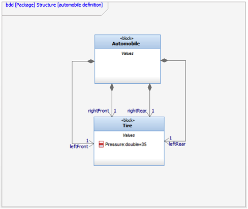
Now, everywhere the tire is used (or the Tire block is used to type a Part, such as leftfront:Tire, leftrear:Tire, etc.), the default value of Pressure will be 35.    This value is not contextualized… Every tire on the car has a value of pressure that is exactly 35.

18.tire_ibd

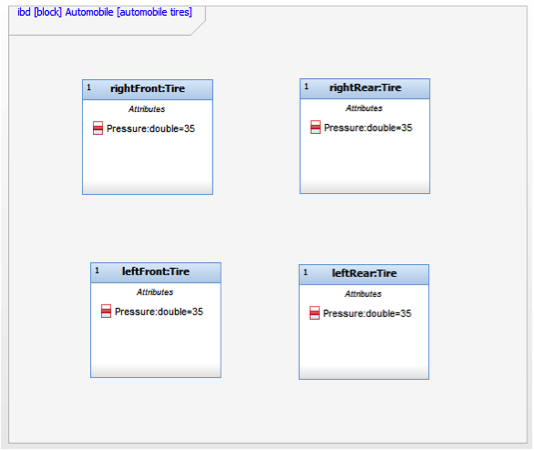
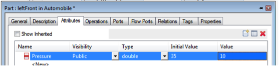
Is that realistic?  No, but it may be adequate as a starting point.   SysML provides a couple of way to specify pressure such that the value of leftfront:Tire.Pressure can be different from the value of leftrear:Tire.Pressure.  Through the arcane concept of property specific types, the modeler can re-define the initial value for a particular context.  Rhapsody can actually do this pretty well.  Just open the attributes on leftfront:Tire and insert a new value:

19.pressure_value

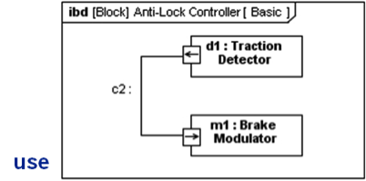
And here’s what happens on the ibd:

20.tire_ibd2

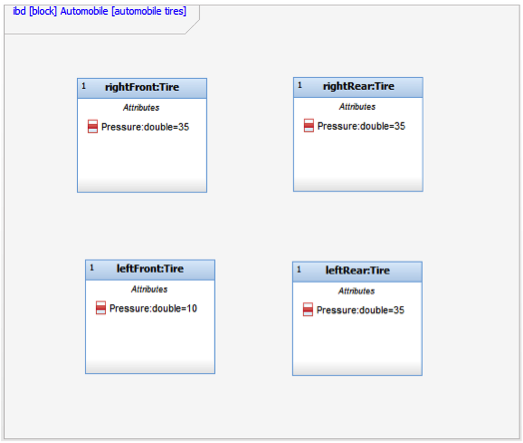
The other mechanism SysML uses for context specific values is instance semantics.  These can actually be more robust than redefinition of values, but tool support of this concept seems to be inconsistent.  Readers are highly encourage modelers to consult the INCOSE MBSE Wiki, and particularly the Telescope MBSE Challengeto see how they managed to resolve analysis issues without directly using contextualized values in SysML.    A SysML descriptive model can still fulfill the role of a system design document or specification without contextualized values…  it is just more powerful if it can address contextualized values!

As shown by the tire example above, it is entirely possible to specify values without identifying meaningful Value Types.  Analysis routines and equations don’t use units and dimensions (a.k.a “quantity kinds”), they just crunch numbers.  It is the systems engineers that have to keep track of the units, and manually insert conversion factors in the code!  In fact, Phoenix MBSEpak works just fine without units and dimensions!  The website for the InterCAX family of plug-ins has demonstrated use of value types (perhaps with full units and dimensions) for MagicDraw, Artisan Studio, and Enterprise Architect.  They only have demonstrated the “Real” attribute type in Rhapsody, but as a company InterCAX is aware of the metrology required to track and transform values between units, and is attempting to incorporate that into their tools.

A textual requirement may specify a particular value, such as in a specification document or table.  When such values appear, they always include the units.  The overall requirement may captured as a text string attribute of a SysML Requirement element, and the value may even be exposed for explicit binding to a parametric evaluation constraint (MBSEpak includes just such an extension mechanism to SysML).  The units associated with the value in the requirement, however, have not been so well treated.  It is currently up to the modeler to keep track of the units and conversion factors.

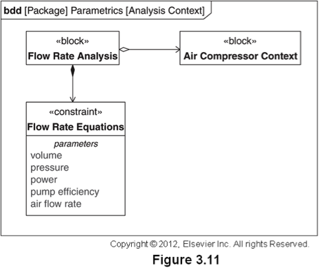
A SysML Value Type is used, obviously, to type a Value Property. It ties together a Unit, along with a Quantity Kind (previously known in SysML as “Dimension).  The Quantity Kind can be length, surface area, volume, mass, etc.  Values may be transformed from one type of Unit to another, as long as they have the same Quantity Kind.  By using a standard formalism for Units and Quantity Kinds when establishing Value Types, we are building the ability to automatically transform values into our models.   The good news is that a standard library of Value Types, Units, and Quantity Kinds can be imported into your SysML model as a library, so you don’t have to reinvent anything.   In fact, the SysML specification includes an appendix that defines SI Units and Quantity Kinds, and most tools have codified this library and made it available.  Once these Value Types are available in the model, they can be used instead of the standard “string, double, float” etc. Attribute types when defining a Value Property.  If you use a good Value Type library, unit conversions can become automatic.

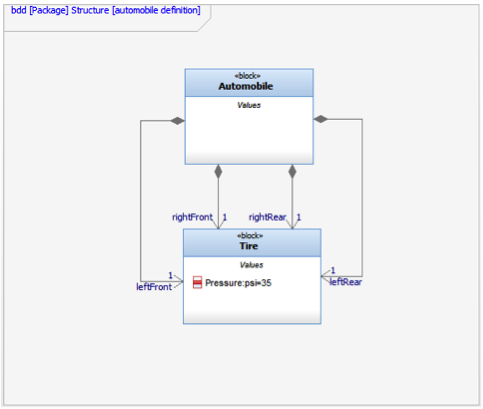
Back to our tire example, the Dimension pressure, the Unit pounds per square inch, and the Value Type psi have been defined.  This could have been done using a library, but this way the browser is less cluttered for example purposes.  Also included is the unit newton-meters, but that is actually inconsistent with pressure.  This is a mistake… the modeler originally meant newtons_per_meter^2, but the author left it in the example because it makes a good point.

21.units

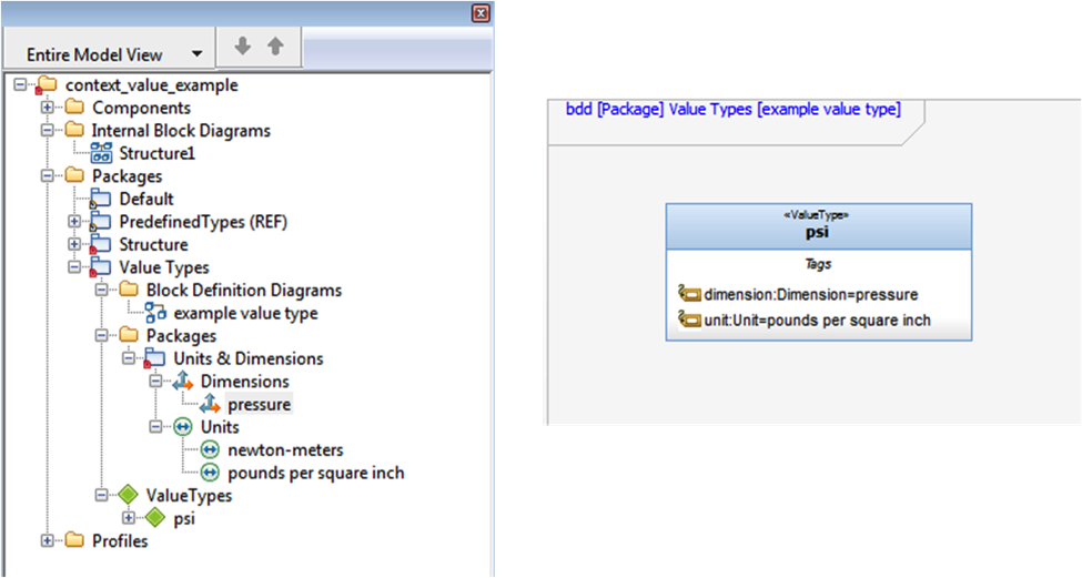
This Value Type was then applied to the attribute Pressure.  Of course, this only had to happen once, and all the usages of Tire were also updated.

22.tire_bdd3


Note that each domain will need to extend the “standard” Value Types library to include things that are unique to that domain.  PK (probability of kill) for instance is unique to military applications.  PRA (probability of raid annihilation) is unique to air defense.  The reader is sure to think of others.

Readers are highly encouraged to walk through the ESA Telescope Model online, paying particular attention to their treatment of units & dimensions (look under “MD Customization for SysML::SI Definitions” and  “QUDV Library”), and parametric analyses (“APE::APE_Performance”).


Modeling functionality vs. model execution.

Sooner or later, every system modeler will come across the concept of “model execution“.  During the 1990’s, “executable system models” seemed to be all the rage among forward-thinking systems engineers (like me), right up there with “object oriented systems engineering”!  There were a number of system modeling tools that explicitly supported the notion of executable system models, notably Ascent Logic Corporation’s RDD-100 and Vitech Corporation’s CORE.  The author personally used RDD-100 on several programs, and is also familiar with CORE.  Both are based on the Alford/Long SREM methodology, which provides sufficient rigor that the models may be machine interpretable, and thus executable.  Behavior is represented using behavior diagrams (RDD) or enhanced functional flow block diagrams (EFFBDs) (CORE), and this is managed separately from the system structure.  Model execution imposes physical constraints on the execution of the designed behavior.  Note that these tools were developed before UML or SysML were available.

Proponents of “model execution” claim that it provides the only way to check the dynamic consistency of the model.  Executing the model in a tool like RDD-100 or CORE provided a way to animate the behavior diagrams, consistent with the resources and constraints imposed by the physical structure as modeled.  This quickly exposed race conditions, starved resources, and lockouts or logic errors.   It did not, however, accurately model overall system performance, nor was it intended to!  This executable system model is still a descriptive model, not an analytical model.   This is an important distinction… When detailed design or environmental details are added to a system model, it looses its value as a well balanced, clearly bounded system design framework!  System model execution is not a substitute for a robust analysis plan, and will not take the place of a modeling and simulation effort!

Consider this dramatic example of this kind of mis-application:  One presenter at an early RDD-100 National User’s Group conference described how he successfully modeled the complete set of low-level network bus protocols, and simulated a multi-node computer network… all on a tool that doesn’t even compile!  He seemed quite proud of the fact that each simulation run took about a week!  He could have done the same job in OPNET in a matter of minutes.

It’s important at this point to distinguish between “executable models” and “code generation” or the generation of code, which may in turn execute.  In the RDD-100/CORE tradition, the term “executable model” implies that a comprehensive simulation environment is included in the tool and is available for use by the systems engineer/modeler.  In fact, RDD-100 did not generate code at all, and it did not compile… It ran interpretively in a huge SmallTalk image file, and was extremely inefficient from a computational perspective!  There are a large number of UML based tools that can generate code.  Just because they can generate code does NOT mean that they can build “executable system models”!  The simulation environment and the initial conditions must also be available and easily manageable by the modeler before I would declare any tool capable of building executable system models.

So here is the author’s assessment of the “burden” of model execution: In addition to a semantically correct system behavioral model, the tool (and modeler) need also to support:

  • A simulation environment, including means for keeping track of simulation time and resources
  • A stimulus generator or input file.
  • A visualization/animation capability … Not just animating the diagrams, but providing a way to track how values change over time, including any outputs.  Sometimes, animation of a mockup HSI is important.
  • A way to monitor resource constraint/utilization based on how behavior has been allocation to structure

The Rhapsody folks have promised to incorporate a simulation engine into the tool, but the author has not seen it operate yet.  It is certain to be based on the existing code generation capability of the tool.  MagicDraw and Artisan Studio also claim to have model execution capability.  Experience has shown that maintaining a goal of model execution will significantly restrict how behaviors can be represented in these tools… for example, functional hierarchy is impossible in Rhapsody if you want to generate code (or presumably execute).

One could logically ask why Matlab, Simulink, or Extend couldn’t be used to provide system model execution… clearly that they can, but one must question their ability to adequately represent an abstract descriptive system model.  Simulink has improved significantly over the years, and it handles abstraction a lot better than it used to.  If clear segregation of form and function is important, however, the author doubts that these system level simulation tools are up to the task yet.  This is an area for further inquiry.

If model execution is so good, then why would anyone NOT want to make their system models executable?  In a word, time.  It takes a great deal of time to take an already useful descriptive system model and make it animate properly.   One of the conclusions reached during the CC&D Pilot project was that it took just as long to get a system model to animate as it took to build it in the first place.  Of course, this was using a code generation tool, not an executable system modeling tool, which significantly extended the effort required.  Derek Hatley, while teaching a class in 1994, made it clear that he considered model execution to be a waste of time.  He argued that race conditions and lockouts are discovered by simple static analysis, without the need for a simulation.  This may be true, but it is certainly compelling to see the diagrams animate, and to generate event traces from the model directly.

I often hear the criticism that “SysML doesn’t execute”, which is perfectly true.  SysML was not  inherently designed execute, nor was it designed to calculate (see the parametrics section).  It was designed to be compatable with emerging UML standards for executable semantics, such as Foundational UML (fUML),and it’s associated action language (Action Language for fUML, a.k.a. “ALF“).    Some SysML tools are beginning to incorporate fUML, but it has yet to be leverage to provide SysML model execution.

There is hope that a SysML model could be linked or transformed in a way that could accommodate execution in Simulink or Extend.  While this may eventually be possible, most attempts so far have involved manually re-building the SysML model in the other tool.  This quickly leads to model maintenance and configuration difficulties. Rhapsody for example provides a way to incorporate Simulink modules as blocks in a SysML model, but that’s really not the same thing.

So, should you invest in making your SysML model executable?  There are certainly advantages, not the least of which is that it will motivate your modeling team!  It also provides a good milestone for model completion and maturity.  It is strongly advised to keep “model execution” from becoming an analysis activity in its own right, and if you do execute, do it in as abstract or unrealistic way as is tolerable.  Leave realism to the Modeling & Simulation experts!