
Understanding the difference between diagrams & models
PowerPoint & Visio teach us to take diagrams at face value. Diagrams in these tools can be manipulated independently, arbitrarily modified, and easily abstracted. Anyone can add whatever they want, without rigor or process. As a result, we treat a set of diagrams as unrelated pictures. The better modeling tools tend to reinforce this impression… They provide a palette of drag and drop symbols and line types, and even include resizing and shading options just like Visio or PowerPoint. This is great from a user familiarity perspective, but terrible from a model integrity perspective. These tools make it much easier to create a new “box on a diagram” (and corresponding model element) than to find and use an element that is already in the model.
It has been found that mature modelers work mostly from the model browser to populate diagrams, rather than from the tool palette. In general, it has proven to be good practice to create a model element in the browser first, making sure it is in the package where it needs to be, and then drag that element from the browser on to the diagram. Mature system modelers often scorn using the tool palette, and populate most model elements in the browser without using a diagram at all! This is analogous to creating the parts list before working on the assembly drawing, and it serves to instill an appropriate level of rigor in the modeling process. By building the package/containment structure for the model first, before building a single diagram, the modeler has a better sense of the model as a whole. By populating the initial set of model elements into this structure, the modeller is already invested in maintaining that structure, and already knows where to find things in it. It is even possible in most tools to create relationships between model elements in the browser, but that tends to be more easily done on diagrams.
Once the modeler has the structure of the model firmly in mind, the diagrams become merely convenient views into the model. Each modeling tool is capable of rendering or updating a diagram directly from the model, including following the various relationships (like composition) and rendering the related model elements on the diagram. When these new elements appear, most tools have a variety of auto-layout options for arranging them… but none are totally satisfactory. Diagram layout is the domain of human aesthetics, and machines just aren’t there yet. Tools can also render existing relationships between elements already displayed on a diagram, but that requires an extra step on the modeler’s part. Relying on this diagram rendering capability really starts to expose and exercise the power of building models in the first place. The modeler becomes focused on the model, not the diagram.
It is also important to remember that reports, scripts and checkers run on the Model, not the diagrams! It doesn’t matter how pretty the diagrams are if the model is inconsistent. Modelers who really focus on the model soon realize that tables and matrices are also excellent model viewers. For example, advanced system modelers very rarely want to see a requirements diagram, and prefer to see requirements in a table of some kind. They also tend to prefer to see allocation relationships in a matrix, rather than on a diagram.
This emphasis on model vs. diagram doesn’t mean that we have to ignore everything we learned using Visio or PowerPoint! Good modeling practices are consistent with good diagrams, and the following principles still apply:
- Minimize number of elements at each layer of abstraction (5-7 elements is the standard practice)
- Elide unnecessary information on the diagram… use views/viewpoints to aid with auto-generation. Try to make a diagram fit on a single page/screen
- Give the diagram a meaningful name! Be explicit about what it is supposed to represent.
Diagram frames are, in my mind, one of the most useful and meaningful advances of SysML over UML. SysML requires EVERY diagram to have a frame, and the frame actually means something… The diagram frame represents an element already in the model, so the frame provides a context to understand everything inside it. The diagram header is used to specify exactly which model element the diagram frame represents.
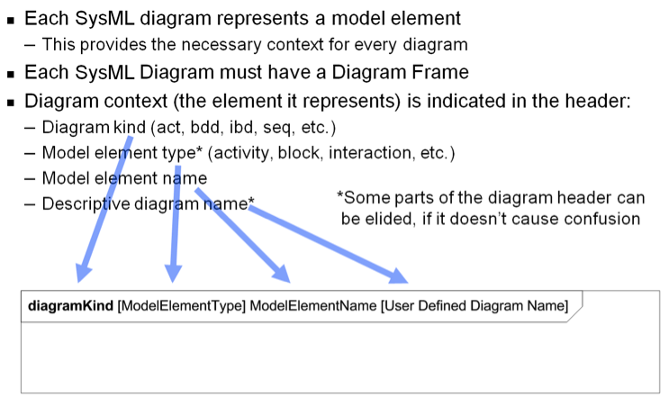
There have been complaints about how cumbersome it is to read these diagram headers… but once the modeler is thinking in terms of the model, rather than the diagram, the information in the header is invaluable!
Recent Comments