
How much SysML do you really need to know?
The complaint is frequently heard that “SysML is too complex” and “It is impossible for non-software, non-UML systems engineers to learn!” This typically comes from folks who aren’t familiar with system modeling at all, rather than those with modeling experience who could be considered qualified to judge the complexity and adequacy of a modeling language. Their implication is that they need to understand ALL of SysML in order to use ANY of it. This is the fundamental stumbling block this blog entry intends to address.
Here is the scope of diagrammatic complexity the SysML learner is confronted with when trying to understand the various diagrams encompassing SysML:
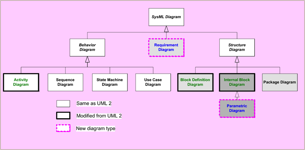
This is consistent with UML, and should be a small logical step for the UML literate modeler. But it can be understandably daunting to the systems engineer who is unschooled in modeling. Do they have to understand the subtleties of all of these diagrams? Of course not! This “standard” taxonomy also does not consider the similarity between the various diagram types. Much of the angst that new SysML learners experience can be relieved by pointing out that there are really only three diagrammatic concepts that they need to learn in order to start modeling:
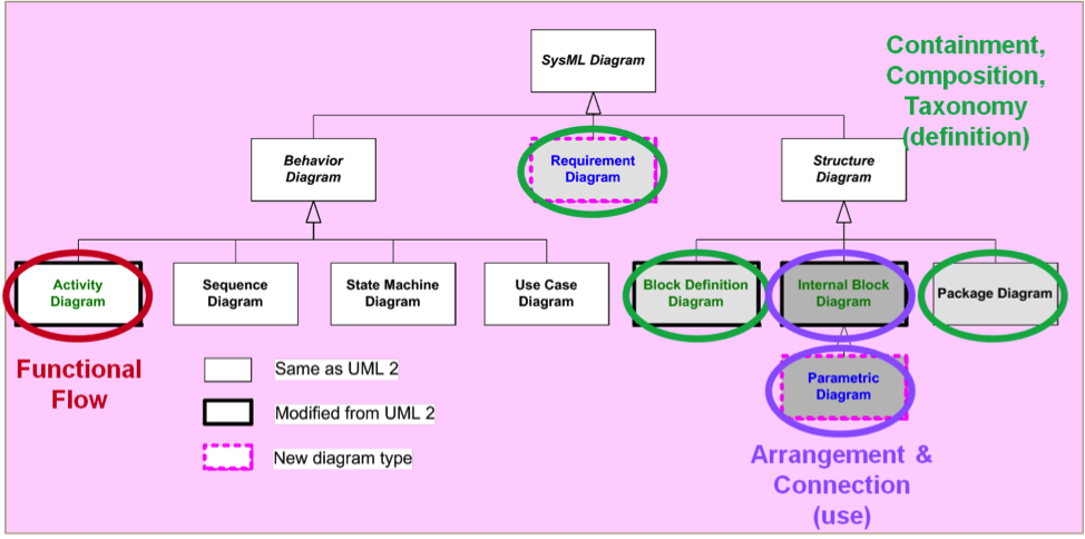
- Arrangement and connection (use), as shown on internal block diagrams and parametric diagrams. This is the most intuitive, boxes-and-lines representation. Everyone “gets” this, because it is a standard “system block diagram” notation. It only gets confusing when the student is prematurely foced to think about typing parts via blocks, or typing ports. The basic untyped part and connector is always easy to grasp. Unfortunately, in the long run, these simplistic concepts aren’t very useful. The concept of blocks typing ports is appropriate to introduce after the student has put the third part on an IBD with the same name. If the parts really are the same, then the instructor has an entre into discussing blocks as a way of defining parts.
- Containment, composition, and taxonomy (Definition), as shown on block definition diagrams, package diagrams, and requirements diagrams. This starts to introduce new symbols that a systems engineer may not be familiar with, such as black-diamond composition. However, every engineer is familiar with the concept of parts lists. Most people “get” bdd’s when they are presented as a parts hierarchy. The subtleties of role/part names vs. Block names can be explained as part number vs. Catalog number, e.g. “R5 is the drain resistor in the circuit. It is a 500ohm, 1/4 watt resistor, Jemeco catalog number 1967344”. 1967344 is the block and provides the definition, R5 is the part and provides the context/use.
- Most “old school” systems engineers are familiar with functional flows of some kind, and are less comfortable with state machine representation. Functional decomposition can be accomplished using activities on bdds. Functional flow needs something like activity diagrams. Yes, there is a convention here to learn that is different than IDEF 0, N2, or other formats… But it does include “old school” concepts like segregating control and data flow. “old schoolers” familiar with Operational Concept Diagrams already know about swimlanes, and should be pretty comfortable picking up activity diagrams with swimlanes/partitions.
These three diagrammatic concepts are all that are normally required for a new-to-modeling systems engineer to begin to be productive. It doesn’t have to be intimidating!
Recent Comments